Monday, August 31, 2009

My shield collection

While waiting for the bulk of Wiseduino PCBs to arrive, I was thinking of showing off my, rather modest, collection of (professional) Arduino shields.


It consists of:
    • Wave shield, from adafruit;
    • Ethernet shield, from nuelectronics;
    • LCD keypad shield, from nuelectronics;
    • Motor shield, from adafruit;
    • Color LCD and joystick shield, from nuelectronics;
    • LED matrix shield, my own creation, used in Wise Clock;
    • Protoshield, from NKCelectronics.

    Related posts:

    Sunday, August 30, 2009

    Testing Wiseduino - EEPROM

    This is the second post related to the testing of Wiseduino. The first one talked about RTC and it started by showing how to correctly plug in the FTDI cable or the FTDI breakout.

    Now lets move on, to the external EEPROM, a 24LC256 memory chip, with a capacity of 32KB. It is connected on I2C (analog 4 and 5) and uses the Wire library to talk with the microcontroller.

    We will test the EEPROM by loading some text from a file. This is how this works: a program on the PC reads the text file and sends the characters to Wiseduino, which, in turn, is running a sketch that reads the incoming characters and saves them to EEPROM.

    Download the sketch here.

    Some VBscript code is included at the bottom of the pde file. Cut and paste that VBscript code into its own file, and name it writeFileToCom.vbs, for example (the extension vbs is mandatory). (This is tested and working on Windows. On Linux or Mac OSX, this script needs to be re-written.)

    How this works was explained earlier, in this post.

    With the eeprom_quotes.pde sketch uploaded, Wiseduino waits for characters to be received from the PC. Now execute the writeFileToCom.vbs VBscript by double clicking on the file (Windows associates the file with its script engine, wscript.exe).
    The VBscript opens the file C:\docs\quotes.txt, reads 10 characters at a time, then sends them over the serial port, until the end of file is reached.
    Two things are required in preparation for the text transfer:

    1. create the C:\docs\quotes.txt text file (or download this file to c:/docs);
    2. in the VBscript, change the COM port number from COM7 to the one you are using;

    The process of transferring the content of the file takes about 10 minutes for a 32KB of text at a baud rate of 9600.

    We check that the text was saved correctly in the EEPROM by reading its content. We will use the same eeprom_quotes.pde to read data from EEPROM. To do this, open the serial monitor, then type "\l" (backslash, lower l) in its input box and hit "Send" button. The bottom window should start displaying the lines of text stored in the EEPROM.


    Related posts:

    Testing Wiseduino - Real Time Clock

    Updated Oct 4, 2010
    The most recent version of Wiseduino has pin 4 of the FTDI connector wired to Vcc (5V). Therefore, when the FTDI connector is plugged in, the board is powered.

    With the Wiseduino board assembled, we can start testing it by uploading some sketches.

    To upload the sketches, you would need the FTDI cable or the FTDI breakout.
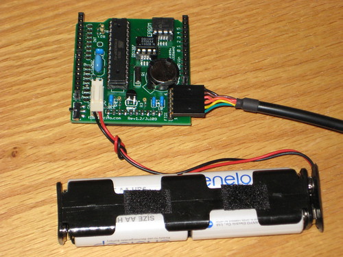
    Make sure that the FTDI cable or the FTDI breakout are plugged in correctly, as shown in the photos below.


    Also, make sure the board is connected to power (preferably 4 AA rechargeables) and the power switch is in the upper position, as in the above photos. This is because pin 4 of the FTDI header, with 5V coming from FTDI, is not connected to the board. There were two reasons behind this decision: 1) a switch between the external power and FTDI should have been used, and 2) FTDI cables and breakouts come in 2 flavours, 5V and 3V3.

    Never power Wiseduino with more than 5V.
    Do not connect the supplied battery snap to a 9V battery because it will damage your Wiseduino. The snap is for battery holders, normally holding 4 AA rechargeables (as in the above photo).


    After launching the Arduino IDE, make sure the right board and serial port are selected, as shown in the images below.


    Lets start by testing the RTC. First, download this sketch and install it (unzip it) in the arduino/hardware/libraries folder. A new folder, named rtc, will be created, and it will contain the RTC class (courtesy of Arduino playgroung) and the rtc.pde sketch in the examples subfolder.

    Load the sketch into Arduino IDE (13 or later). Change the time in setup() function, then compile it and upload it to the board.

    The sketch sets the current time into the RTC:


    void setup()
    {
      Serial.begin(9600);
      RTC.stop();
      RTC.set(DS1307_SEC, 20);
      RTC.set(DS1307_MIN, 49);
      RTC.set(DS1307_HR,  19);
      RTC.set(DS1307_DOW,  4);
      RTC.set(DS1307_DATE,22);
      RTC.set(DS1307_MTH,  1);
      RTC.set(DS1307_YR,   9);
      RTC.start();
    }

    then, almost every second, it retrieves the time from the RTC and it displays to the serial monitor:

    void loop()
    {
      updateTimeBuffer();
      delay(1000);
    }


    void updateTimeBuffer()
    {
      int rtc[7];
      RTC.get(rtc, true);


      int second = rtc[0];
      int minute = rtc[1];
      int hour   = rtc[2];
      int day    = rtc[4];
      int month  = rtc[5];
      int year   = rtc[6];


      Serial.print(hour);
      Serial.print(":");
      Serial.print(minute);
      Serial.print(":");
      Serial.print(second);
      Serial.println("");
    }

    After uploading the above sketch once, the RTC has the current time and it will keep the time even when the Wiseduino board is not powered (due to the onboard backup battery). Now, modify the rtc.pde sketch by commenting out all lines in setup(), except Serial.begin. This will ensure that the microcontroller does not set the RTC every time the board is reset or powered.

    Next, let's play with the EEPROM.

    Related posts:

    Friday, August 28, 2009

    Assembling Wiseduino

    Updated Feb 11/10

    This is the documentation with instructions for assembling the Wiseduino board.
    Basically, this is a list of the steps for preparing, placing and soldering the components.

    I assume that Wiseduino is not the first board you solder and you have more than basic soldering skills.

    I have to be honest and acknowledge that, trying to follow the high standards set by ladyada in her tutorials, I failed. Now I appreciate those tutorials even more. (I suspect that a second person took photos of her soldering; otherwise, using the timer is a gamble.)

    So, let's just say that you already know, from previous projects, how to bend the IC's terminals before inserting the ICs in their sockets, you already know to cut the terminals that stick out (resistors, transistors etc) on the soldering side, you already know that polarity is important for some components (e.g. polarized capacitors) etc.

    Here is the assembly process, step by step:
    1. If you have the SMD version of the EEPROM (24LC256) or RTC (DS1307), solder those first. To make it easier, flux the pad(s) with the flux pen. If not soldered first, it will be harder to access the SMD pads later. Pay attention to the orientation of the chip. Pin 1 is marked with a dot, on both the chip and PCB.
    2. Next, solder the sockets for the microcontroller, EEPROM and RTC (if you have the through hole chips). The notches on the sockets should match those in the silkscreen.
    3. Solder the battery holder. Make sure it is inserted all the way.


    4. Next, solder the power connector, then the 6-pin FTDI header.
    5. Place the micro switch on the pads and solder the middle terminal so that the switch's lever is just 1 mm out of the board's edge. After the micro switch is positioned correctly, solder the other 2 terminals.


    6. Next step is soldering the resistors. All 4 of them need to be inserted and soldered vertically. For this, one of their terminals needs to be bent 180 degrees.
    7. Insert and solder the 4 capacitors.
    8. Next, solder the 16MHz resonator.
    9. Before soldering the crystal for RTC (32,768 Hz), bend its terminals, with pliers, to 90 degrees, about 2 mm from their base. This allows the crystal to stay parallel and close to the board.


    10. Break the 40-pin female header into 4 pieces: two 8-pin headers and two 6-pin headers. This is done by removing one pin, then cutting with a wire-cutter along the empty place.
    11. Position the headers in their locations, then turn over the board and let it stand on the headers, making sure that they are perpendicular to the board. Now solder all four headers.


    12. Solder the transistor, placing it to match its shape in silkscreen.
    13. Optionally (if you want to use the XBee adapter), insert the 10-pin female header on the other side (not the parts side) of the PCB and solder its pins on the parts side.


    14. Insert the chips (ATmega328, 24LC256, DS1307) into their respective sockets, paying attention to their orientation, by matching the notches on the chip with the notches in the socket(s).
    15. Carefully insert the cell battery into its holder. Place the cell under the two plastic stoppers, then gently push the cell down against the lateral contact (it helps if that contact is lifted up a tad, from the hook, with a small screwdriver).
    The assembled board should look similar to the one below.


    A few clarifications and explanations about the Wiseduino board:
    • the FTDI header does not have the 5V power pin connected; therefore 5V needs to be supplied from the 2-pin power connector, usually 4 AA rechargeable batteries;
    • the power slide switch turns the power on when its position is up (towards the top of the board);
    • the board does not have standoff mounts because of the XBee adapter that can be placed on the back; in Wise Clock, the board is standing on its edge, with the LED matrix shield plugged in; should the board need to be mounted (without the Xbee, obviously) to a case or some other surface, I recommend using velcro (with sticky tape on one side);
    • the row of headers parallel to D0-D13 headers is designed to be used with .1" prototype board, similar to Seeeduino (Arduino clone from seeedstudio);
    • 3V3 is provided by the XBee adaptor, only if that is plugged in;
    • the INT pin (from RTC), can be connected to digital pin 2 or digital pin 3, to generate interrupts;
    • an FTDI cable or an FTDI breakout are required for uploading (and communicating) with Wiseduino;
    • there is no reset button, since there is always a shield (with reset button) above the Wiseduino board;
    • to conserve battery in sleep mode, the power indicator LED was dropped (that would have added 10-20 mA).
    Related posts:

    Sunday, August 23, 2009

    Dear customers,

    Thank you for your orders. I am overwhelmed, literally.
    I don't know yet what happened, but I got flooded, all of a sudden, with orders.
    I thought of replying to each of you individually, so I apologize for changing my mind and doing it publicly, but I wanted to include the future customers as well.

    So here is what the situation is: I ran out of some parts, including the boards.

    I am able to ship kits to the first few buyers (I will notify you by email to confirm I shipped the kits on Monday, Aug 24).
    I expect to get a new batch of PCBs in 2 weeks, so the kits will go out as soon as I receive the mising parts.

    For those of you who want to reconsider your order (and cancel) because of the delay, I will refund your money. Just email me, and I will proceed accordingly.

    Again, I apologize for the delay, it was really an unexpected event.
    FlorinC

    Friday, August 7, 2009

    Wise4Sure - now featuring ATmega644

    Last night I was able to finish the prototype of Wise4Sure. The board has ATmega644 as its core, as well as an SD card socket plus the additional circuitry (voltage divider resistors, 3V3 regulator), an RTC with DS1307 and backup battery, and a connector for the 16x32 LED display from Sure Electronics (hence its name).


    Amazingly, after the few modifications, required by ATmega644, of the SDuFAT and Wire libraries, it worked from the first try.

    Following are photos of the assembled and partially encased Wise4Sure project. It contains the LED display attached to the plexiglass panel, and the Wise4Sure board plugged in the back of the display. Power is provided through either FTDI or USB connector.


    The 4KB RAM of ATmega644 should allow for more complex applications, including IR control, wireless (XBee) communication, networking (Ethernet), X10, wave playing etc. Really looking forward to the expanded capabilities. (With ATmega328, I was barely able to combine reading from the SD card with outputting on the LED display.)

    Next step would be the design of a proper PCB.

    Thursday, August 6, 2009

    My duino collection

    It looks like I have more duinos that I will ever use, especially considering that I make my own boards now. Some of them (BBB, Illuminato) were never used, I don't even know if they work :)
    They will go into my time capsule. I am wondering if someone will recognize them 50 years from now.
    From top left:
    • Arduino Duemilanove with ATmega168;
    • Seeeduino v1.1 (ATmega168);
    • Freeduino v1.16 (ATmega168);
    • Wiseduino v1.3 (ATmega328), designed by myself;
    • Illuminato (ATmega845) from liquidware.com;
    • Arduino Pro (ATmega168) from sparkfun.com;
    • Bare-Bones Board rev. C (ATmega168) from moderndevice.com.

    P.S. It seems that I am one of the 100 buyers of the Illuminato. Maybe it will become a collectible item, or more, a piece of history, worthy of Computer Museum. We shall see.

    Related posts: