Sunday, March 29, 2015

Modding WiFiChron with GPS or Bluetooth

The latest revision of WiFiChron has an XBee socket (beside the ESP8266 8-pin socket), which allows the addition of a few individual features:
  1. GPS-based time synchronization, by using the GPSBee;
  2. displaying messages sent from a Bluetooth device, by using the BTBee/BLEBee;
  3. displaying data acquired from an XBee/ZigBee network of sensors (not implemented yet);


Things did not go smoothly, without some drama though. Naively (I always seem to forget that there is a difference between theory and practice), I designed the XBee/ESP to connect to the serial port, with the expectation that once the development (including testing with debug statements to the serial monitor) is done, I will just plug in the serial module (either XBee of ESP8266) and things will work properly. Well, I had to re-consider this approach once again. Luckily, I had two pins left available (D7 and D17), which I could use for software serial. I re-wired those to the XBee/ESP and used the hardware serial for console communication. Until the next board revision, anyone wanting to follow will need to re-route a couple of traces manually, as shown in the photos below (cuts are red-circled).


A few details on my implementation of the GPS time sync (so that one doesn't need to look at the code to figure it out):
  • user can set a timezone (stored in eeprom, default is -1); there is no (easy) way to determine if the timezone was set or not, since -1 (eeprom byte being 255) is a valid value;
  • estimate the timezone from the longitude, assuming that a every 15 degrees is an hour difference;
  • a difference between GPS estimated timezone and the user-set timezone of more than 2 hours would mean that the time is way off and the user did not set the timezone; in this case, blink the display; a difference of 2 hours or less would be acceptable (for many reasons, including summer-time, or variations from the "15-degrees-longitude-per-hour" approximation);
  • in any case, the minutes and seconds are set from the GPS data;
  • date and day are not set/synchronized at all (currently);
  • the GPS sync is scheduled to happen every 10 hours (and also after a reset);
  • a successful sync is indicated by an up arrow at the end of the scrolling date (e.g. March 29, 2015 ^).
I will publish the code as soon as I have a chance to polish it (and also test it with BTBee).

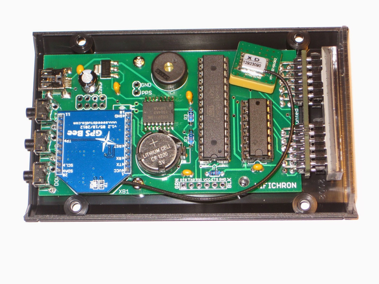
As you can see in the photo below, the GPS antenna fits well in the case. It also works well: the GPS has good reception inside the house, 5 meters from the closest window.


Tuesday, March 17, 2015

How to assemble the 2-servo mini pan-tilt kit

Mystery solved!

This is somehow embarrassing, but I post it anyway, hoping that it may help others.

Although it looks easy, I had trouble assembling the mini pan-tilt kit from adafruit, specifically the bottom servo. I just couldn't figure out how to fix the servo with screws to the main arm, since there are no holes for screws (unless I drill them myself). Also, there is no guide anywhere to be found (uncharacteristic for adafruit), nor explicit photos of the assembled parts. I thought that there must be a trick, so I bought the assembled version as well. Guess what? The "trick" is obvious, and I missed it because I was focused on using the screws! The bottom servo must be inserted in the 2 tracks on each side of the two symmetrical parts that make the arm, no screws needed!

When assembling the kit, the easiest way is to start by attaching together the 2 symmetrical parts of the arm, with the servo between them. (In the photo below, i was too lazy to completely dis-assemble the 2 halves of the arm, I only pulled them apart enough to fit the servo in between, with servo's bracket in one of the tracks.) Notice the servo's bracket snug in the groove.


See? No screws on either side of the servo! Because they are not needed!


I hope these photos will bring some light and spare the frustration to (probably very few) people like me.

Friday, March 13, 2015

WiFiChron with software support for ESP8266

Another great software update from MikeM (download here)! This one has support for the ESP8266 module, allowing the WiFiChron clock to:
Before getting excited and jumping to compile and upload the new sketch, there are a few steps to be done on the ESP8266 module:

1. pull the CHPD pin high with a 10k resistor to Vcc;

2. make sure you can communicate with the module using a serial port; this could also include checking the version of the installed firmware (AT+GMR);

3. upgrade the firmware on ESP8266 to version 0.9.6.

After you download the bin files, the next step is to find a tool that would upload those bin files onto the chip. There are many tutorials on how to do this, some sketchy and ambiguous, some detailed and very helpful. In my search, I found references to a few different tools: XTCOM (old MFC Windows app), "NODEMCU Firmware Programmer", ESP flash downloader, ESPtool (python).

The easiest one to use for me seemed XTCOM, with my only complaint being that COM port selection was limited to COM1-6. Luckily, on Windows XP I am using, I was able to change the serial port from the default (assigned by the OS) COM9 to COM2 (the only one available in the range COM1 - COM6). I used this tutorial to load this firmware.

4. Change the baud rate from the default (after firmware upgrade) 115200 to 38400, for the following reason: according to the datasheet (table 20-6, page 189), ATmega328 running at 8MHz has an error rate of approx. 8% communicating on serial port at 115200.

Now, with the ESP8266 module prepared and plugged in, to connect to your wireless network, you will need to configure the module by providing the SSID and the password. To start this process, select "Init" for the "Wifi" menu item. There is an additional "init y/n" option to confirm the init. Once in "init" mode, the ESP8266 module starts acting as access point (another wireless network), using the SSID "WiFiChron". Connect to it using the key "WiFiChron" (*).


The clock will display (scrolling) an IP address, something like "192.168.4.1". Connect to the WiFiChron's access point with your computer/laptop/tablet/phone and web-browse to that IP address, as shown in the screenshot below.


Use that page to configure your local access-point SSID and key.  You can also configure an optional SNTP host for synchronizing time and an optional RSS URL.  Fill in something like pool.ntp.org for the SNTP host or http://w1.weather.gov/xml/current_obs/KNYC.rss for the RSS URL.

Clicking on the "Submit" button will send the configuration to the WiFiChron system, which will write it into its eeprom. If you check "Activate" before submitting, the WiFiChron will immediately switch out of access-point mode and attempt to connect to the SSID/key that you've entered.  If you have problems, you can power-cycle the WiFiChron.  It will use whatever settings it has stored in eeprom.

(*) Although the "WiFiChron" network was detected, I could not connect to it from my Windows XP machine (acquiring network address takes forever and eventually fails). It worked much better with my Android tablet. This is the reason why the first screenshot above is from my XP machine and the second is from my tablet.

Update Jan 21, 2020: In Windows 10, connecting to WiFiChron setup page and submitting the parameters works just fine.


NOTE: The ESP8266 module must be taken out of the socket while uploading the sketch (since it's connected to Rx/Tx as well).